下载地址:
http://www.mxcad.net:2080/cpp/ParamDraw.zip
在绘制实体时,我们需要以动态内存的方式来实例化实体,在C++的语法里即体现为使用new关键字来实例化一个实体对象,如:
McDbLine * pLine = new McDbLine(McGePoint3d(0, 0, 0), McGePoint3d(1, 1, 1));
上述代码即初始化一个直线实体对象,现在将它放入模型空间即可显示:
MrxDbgUtils::addToCurrentSpaceAndClose(pLine);
如未指定实体所在图层,该实体会出现在默认的图层。在此,我们绘制了直线、多段线、点、样条线、圆、圆弧、椭圆、椭圆弧等实体,并将它们设置为红色(红色索引值为1),并将其放入一个独立的图层中,图层中设置了线型,颜色;代码、线型、颜色索引如下所示:
McDbObjectId CParamDrawDlg::CreateLayer(const McDbEntity * pEnt)const
{
	auto sTypeName = pEnt->isA()->name();

	McDbLayerTable * pLayer = nullptr;
	//得到当前数据库
	auto pDatabase = MxDraw::GetDatabase(MxDraw::GetCurOcxHandle());
	//得到层表
	pDatabase->getLayerTable(pLayer, McDb::kForWrite);
	McDbLayerTableRecord * pLayerRecord = nullptr;
	//判断层表里是否有该层的记录
	if (pLayer->has(sTypeName))
	{
		pLayer->getAt(sTypeName, pLayerRecord, McDb::kForWrite);
	}
	else
	{
		//如果没有该层,即添加该层至层表
		pLayerRecord = new McDbLayerTableRecord;
		pLayerRecord->setName(sTypeName);
		pLayer->add(pLayerRecord);
	}

	McCmColor mLayerColor;
	mLayerColor.setColorIndex(1);		//红色
	mLayerColor.setColorMethod(McCmColor::kByACI);
	pLayerRecord->setColor(mLayerColor);//
	pLayerRecord->setLineWeight(McDb::kLnWt025);//
	pLayerRecord->setBright(100);//100亮度

	McDbLinetypeTable * pLinetype = nullptr;
	McDbObjectId mLineTypeID;
	pDatabase->getLinetypeTable(pLinetype, McDb::kForRead);
	pLinetype->getAt(L"DIVIDE", mLineTypeID);
	pLayerRecord->setLinetypeObjectId(mLineTypeID);

	//图层必须在关闭状态才能向里添加实体
	pLinetype->close();
	pLayerRecord->close();
	pLayer->close();
	return pLayerRecord->objectId();

}
图层中的线型:
	//设置层为“DIVIDE”线型
	McDbLinetypeTable * pLinetype = nullptr;
	McDbObjectId mLineTypeID;
	pDatabase->getLinetypeTable(pLinetype, McDb::kForRead);
	pLinetype->getAt(L"DIVIDE", mLineTypeID);
	pLayerRecord->setLinetypeObjectId(mLineTypeID);
已有线型:
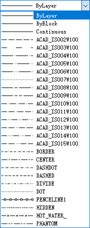
颜色索引说明:
kByblock = 0 随块
kRed = 1 红色
kYellow = 2 黄色
kGreen = 3 绿色
kCyan = 4 青色
kBlue = 5 蓝色
kMagenta = 6 洋红色
kWhite = 7 白色
kBylayer = 256 随层
直线在MxDrawCAD控件下为一个实体类:
class ARXDLL McDbLine : public McDbCurve
通过调用直线类的构造函数
	// -------------------------------------------------------------------------
	// Summary:
	// 		构造函数
	// -------------------------------------------------------------------------
	McDbLine();
	// -------------------------------------------------------------------------
	// Summary:
	// 		由两个点构造函数
	// Parameters:
	// 		start	 -	直线的开点
	// 		end		-	直线的结束
	// -------------------------------------------------------------------------
	McDbLine(const McGePoint3d& start, const McGePoint3d& end);
或使用如下的方式来初始化直线实体:
McDbLine * pLine = new McDbLine;
通过设置函数来改变它的属性,如下:
McDbLine * pLine = new McDbLine(McGePoint3d(0, 0, 0), McGePoint3d(1, 1, 1));
使用通用模板函数来进行设置,该函数代码如下:
template<typename T>
inline void CParamDrawDlg::SetEnt(unsigned short iColorIndex, LPCTSTR pszNewVal, T * pEnt,
	std::function<void(McDbObjectId)> SetLayer,
	std::function<void(T*)> SetEnt)
{
	//获取到设置的相关层
	auto mLayerID = CreateLayer(pEnt);

	//把实体设置成红色,且加入到新层中去
	pEnt->setColorIndex(iColorIndex);
	pEnt->setAlwaysShowLineWeight(true);
	pEnt->setLineWeight(McDb::kLnWt018);
	pEnt->setLinetype(pszNewVal);
	pEnt->setLayer(mLayerID);

	//对于层进行更多的设置
	if (SetLayer)
	{
		SetLayer(mLayerID);
	}
	//对于实体进行更多的设置
	if (SetEnt)
	{
		SetEnt(pEnt);
	}

	AddToSpaceAndPutToView(pEnt);
}
初始化“直线”并调用它:
 	{
 		McDbLine * pEnt = new McDbLine(McGePoint3d(0, 0, 0), McGePoint3d(1, 1, 0));
 		SetEnt(256, _T("ByLayer"), pEnt);//颜色随层,线型随层
 	}

 	{
 		McDbLine * pEnt = new McDbLine(McGePoint3d(0, 1, 0), McGePoint3d(1, 2, 0));
 		SetEnt(0, _T("ByBlock"), pEnt);//颜色随块,线型随块
 	}

 	{
 		McDbLine * pEnt = new McDbLine(McGePoint3d(0, 2, 0), McGePoint3d(1, 3, 0));
 		SetEnt(2, _T("BORDER"), pEnt);//黄色,BORDER线型
 	}
在上述代码中,在将直线实体放入模型空间之前,将直线设置为红色并将该实体类型放入新加入的图层中,在添加模型空间并关闭实体之后,便不能再修改它的属性,但可以通过以打开的方式来修改它,在参数化绘制“文字”时,我调用代码示例如下:
	{
		McDbText * pEnt = new McDbText(McGePoint3d(0, 0, 0), _T("测试1"),
			McDbObjectId::kNull, 5.0, 1.0);
		SetEnt(256, _T("ByLayer"), pEnt);//颜色随层,线型随层
	}
	{
		McDbText * pEnt = new McDbText(McGePoint3d(10, 0, 0), _T("测试2"));
		SetEnt<McDbText>(0, _T("ByBlock"), pEnt, nullptr, [](McDbText * pFuncEnt) {
			pFuncEnt->setAlignmentPoint(McGePoint3d(1, 1, 0));
			pFuncEnt->setHeight(10);
			pFuncEnt->setHorizontalMode(McDb::kTextRight);
			pFuncEnt->setOblique(0.5);
		});//颜色随层,线型随层
	}
	{
		McDbText * pEnt = new McDbText(McGePoint3d(20, 0, 0), _T("测试3"));
		SetEnt<McDbText>(2, _T("BORDER"), pEnt, [](McDbObjectId mLayerID) {
			McDbObjectPointer<McDbLayerTableRecord> spLayer(mLayerID, McDb::kForWrite);
			spLayer->setIsLocked(true);
			spLayer->setBright(100);
//			spLayer->setIsFrozen(true);
			spLayer->setIsLocked(true);
		}, [](McDbText * pFuncEnt) {
			pFuncEnt->setWidthFactor(2);
			pFuncEnt->setColorIndex(4);
			pFuncEnt->setHeight(10);
			pFuncEnt->setRotation(1);
		});//颜色随层,线型随层
	}
这里我们在第三个文字的SetEnt函数中添加了设置图层并打开层表记录,调用调用代码如下:
			McDbObjectPointer<McDbLayerTableRecord> spLayer(mLayerID, McDb::kForWrite);
			spLayer->setIsLocked(true);
			spLayer->setBright(100);
//			spLayer->setIsFrozen(true);
			spLayer->setIsLocked(true);
多段线在MxDrawCAD控件下为一个实体类:
class ARXDLL McDbPolyline : public McDbCurve
通过调用多段线实体类的构造函数:
// -------------------------------------------------------------------------
// Summary:
//  构造函数
// -------------------------------------------------------------------------
McDbPolyline(PolylineType type = kLwPolyline);

McDbPolyline(unsigned int num_verts);
初始化多段线实体,可使用默认的构造函数,如下:
	//使用PL话矩形
	auto DrawRect = []() ->McDbPolyline*
	{

		McDbPolyline * pEnt = new McDbPolyline;
		//添加一些端点
		pEnt->addVertexAt(McGePoint2d(10, 0));
		pEnt->addVertexAt(McGePoint2d(10, 10));
		pEnt->addVertexAt(McGePoint2d(0, 10));
		pEnt->addVertexAt(McGePoint2d(0, 0));

		//设置闭合
		pEnt->setClosed(true);

		return pEnt;
	};

	//使用PL画箭头
	auto DrawTriangle = []()->McDbPolyline*
	{
		McDbPolyline * pEnt = new McDbPolyline;
		//添加一些端点
		pEnt->addVertexAt(McGePoint2d(0, 0));
		pEnt->addVertexAt(McGePoint2d(10, 0));
		pEnt->addVertexAt(McGePoint2d(20, 0));
		pEnt->setWidthsAt(1, 5, 0);

		return pEnt;
	};

	McGeMatrix3d mMatrix;

	mMatrix.setTranslation(McGeVector3d(0, 0, 0));
	SetEnt<McDbPolyline>(256, _T("ByLayer"), DrawRect(), nullptr, [&](McDbPolyline * pFuncEnt) {
		pFuncEnt->transformBy(mMatrix);
	});//颜色随层,线型随层

	mMatrix.setTranslation(McGeVector3d(11, 0, 0));
	SetEnt<McDbPolyline>(0, _T("ByBlock"), DrawRect(), nullptr, [&](McDbPolyline * pFuncEnt) {
		pFuncEnt->transformBy(mMatrix);
	});//颜色随块,线型随块

	mMatrix.setTranslation(McGeVector3d(0, 14, 0));
	SetEnt<McDbPolyline>(2, _T("Continuous"), DrawTriangle(), nullptr, [&](McDbPolyline * pFuncEnt) {
		pFuncEnt->transformBy(mMatrix);
});//黄色,BORDER线型点在MxDrawCAD控件下为一个实体类:
class ARXDLL McDbPoint: public McDbEntity
通过调用点的构造函数:
// -------------------------------------------------------------------------
// Summary:
//  构造函数
// -------------------------------------------------------------------------
McDbPoint();
// -------------------------------------------------------------------------
// Summary:
//  构造函数
// Parameters:
//  position - 点位置
// -------------------------------------------------------------------------
McDbPoint(const McGePoint3d&   position);
初始化,或使用默认的构造函数,代码如下:
	{
		McDbPoint * pEnt = new McDbPoint(McGePoint3d(1, 1, 0));
		SetEnt(256, _T("ByLayer"), pEnt);//颜色随层,线型随层
	}
	{
		McDbPoint * pEnt = new McDbPoint(McGePoint3d(2, 2, 0));
		SetEnt(0, _T("ByBlock"), pEnt);//颜色随块,线型随块
	}
	{
		McDbPoint * pEnt = new McDbPoint(McGePoint3d(3, 3, 0));
		SetEnt(2, _T("BORDER"), pEnt);//黄色,BORDER线型
}样条线在MxDrawCAD控件下为一个实体类:
class ARXDLL McDbSpline : public McDbCurve
通过调用
// -------------------------------------------------------------------------
// Summary:
//  构造函数
// -------------------------------------------------------------------------
McDbSpline(void);
初始化,或使用默认的构造函数,如:
	auto Func = []()->McDbSpline * {
		McDbSpline * pEnt = new McDbSpline;

		//设置端点
		McGePoint3dArray vPts;
		vPts.append(McGePoint3d(10, 0, 0));
		vPts.append(McGePoint3d(10, 10, 0));
		vPts.append(McGePoint3d(20, 0, 0));
		vPts.append(McGePoint3d(20, 10, 0));

		//将上面的端点添加到该实体
		pEnt->setFitData(vPts, 0, 0, McGeVector3d(0, 1, 0), McGeVector3d(1, 0, 0));

		return pEnt;
	};

	McGeMatrix3d mMatrix;

	mMatrix.setTranslation(McGeVector3d(0, 0, 0));
	SetEnt<McDbSpline>(256, _T("ByLayer"), Func(), nullptr, [&](McDbSpline * pFuncEnt) {
		pFuncEnt->transformBy(mMatrix);
	});//颜色随层,线型随层

	mMatrix.setTranslation(McGeVector3d(0, 20, 0));
	SetEnt<McDbSpline>(0, _T("ByBlock"), Func(), nullptr, [&](McDbSpline * pFuncEnt) {
		pFuncEnt->transformBy(mMatrix);
	});//颜色随层,线型随层

	mMatrix.setTranslation(McGeVector3d(0, 40, 0));
	SetEnt<McDbSpline>(2, _T("BORDER"), Func(), nullptr, [&](McDbSpline * pFuncEnt) {
		pFuncEnt->transformBy(mMatrix);
});//颜色随层,线型随层圆在MxDrawCAD控件下为一个实体类:
class ARXDLL McDbCircle : public McDbCurve
通过调用
// -------------------------------------------------------------------------
// Summary:
//  构造函数
// -------------------------------------------------------------------------
McDbCircle();
// -------------------------------------------------------------------------
// Summary:
//  构造函数
// Parameters:
//  cntr - 圆的中心点
//  nrm  -   暂没有使用
//  radius -   圆的半径
// -------------------------------------------------------------------------
McDbCircle(const McGePoint3d& cntr, const McGeVector3d& nrm, double radius);
初始化,或使用默认的构造函数,如:
	{
		McDbCircle * pEnt = new McDbCircle(McGePoint3d(0, 0, 0), McGeVector3d(), 10);
		SetEnt(256, _T("ByLayer"), pEnt);//颜色随层,线型随层
	}
	{
		McDbCircle * pEnt = new McDbCircle(McGePoint3d(10, 0, 0), McGeVector3d(), 10);
		SetEnt(0, _T("ByBlock"), pEnt);//颜色随块,线型随块
	}
	{
		McDbCircle * pEnt = new McDbCircle(McGePoint3d(10, 0, 0), McGeVector3d(), 10);
		SetEnt(2, _T("BORDER"), pEnt);//黄色,BORDER线型
}圆弧在MxDrawCAD控件下为一个实体类:
class ARXDLL McDbArc : public McDbCurve
通过调用
// -------------------------------------------------------------------------
// Summary:
//  构造函数
// -------------------------------------------------------------------------
McDbArc();

// -------------------------------------------------------------------------
// Summary:
//  圆弧的构造函数,圆弧的位置是开始点逆时针转到结束点经过的圆弧
// Parameters:
//  center   - 圆弧的中心
//  radius   - 圆弧的半径
//  startAngle  - 圆弧的开始角,圆弧开始点顺时针转到X轴经过的弧度
//  endAngle  - 圆弧的结束角,圆弧结束点顺时针转到X轴经过的弧度
// -------------------------------------------------------------------------
McDbArc(const McGePoint3d& center, double radius,
double startAngle, double endAngle);

// -------------------------------------------------------------------------
// Summary:
//  圆弧的构造函数,圆弧的位置是开始点逆时针转到结束点经过的圆弧
// Parameters:
//  center   - 圆弧的中心
//  normal   - 暂没使用
//  radius   - 圆弧的半径
//  startAngle  - 圆弧的开始角,圆弧开始点顺时针转到X轴经过的弧度
//  endAngle  - 圆弧的结束角,圆弧结束点顺时针转到X轴经过的弧度
// -------------------------------------------------------------------------
McDbArc(const McGePoint3d& center, const McGeVector3d& normal,
double radius, double startAngle, double endAngle);
如:
	const double PI(3.1415);

	//在X = 100, Y = 100的位置,半径为10,
	//圆弧开始点顺时针转到X轴经过90°,
	//圆弧结束点顺时针转到X轴经过180°的弧
	{
		McDbArc * pEnt = new McDbArc(McGePoint3d(0, 0, 0), 10, PI / 2, PI);
		SetEnt(256, _T("ByLayer"), pEnt);//颜色随层,线型随层
	}

	{
		McDbArc * pEnt = new McDbArc(McGePoint3d(10, 10, 0), 10, PI / 2, PI);
		SetEnt(0, _T("ByBlock"), pEnt);//颜色随块,线型随块
	}

	{
		McDbArc * pEnt = new McDbArc(McGePoint3d(20, 20, 0), 10, PI / 2, PI);
		SetEnt(2, _T("BORDER"), pEnt);//黄色,BORDER线型
}椭圆在MxDrawCAD控件下为一个实体类:
class ARXDLL McDbEllipse : public McDbCurve
通过调用
// -------------------------------------------------------------------------
// Summary:
//  构造函数
// -------------------------------------------------------------------------
McDbEllipse(void);

// -------------------------------------------------------------------------
// Summary:
//  构造函数
// Parameters:
//  center            -  椭圆的圆心
//  unitNormal        -  暂没有使用
//  majorAxis         -  椭圆的主轴向量
//  radiusRation      -  椭圆的副轴长与主轴长的比值
//  startAngle        -  椭圆弧开点位置顺时针转到主轴的角度
//  endAngle          -  椭圆弧结束点位置顺时针转到主轴的角度
// -------------------------------------------------------------------------
McDbEllipse(const McGePoint3d&  center,
const McGeVector3d& unitNormal,
const McGeVector3d& majorAxis,
double              radiusRatio,
double              startAngle = 0.0,
double              endAngle   = 6.283185307179586476925286766559000);
如:
	//在X = 200, Y = 200的位置,
	//圆心向X轴偏移长度为10的向量
	//圆心向Y轴偏移长度为10 * 0.2的向量
	{
		McDbEllipse * pEnt = new McDbEllipse(
			McGePoint3d(200, 200, 0), McGeVector3d(),
			McGeVector3d(10, 0, 0), 0.2);
		SetEnt(256, _T("ByLayer"), pEnt);//颜色随层,线型随层
	}
	{
		McDbEllipse * pEnt = new McDbEllipse(
			McGePoint3d(300, 200, 0), McGeVector3d(),
			McGeVector3d(10, 0, 0), 0.2);
		SetEnt(0, _T("ByBlock"), pEnt);//颜色随块,线型随块
	}
	{
		McDbEllipse * pEnt = new McDbEllipse(
			McGePoint3d(400, 200, 0), McGeVector3d(),
			McGeVector3d(10, 0, 0), 0.2);
		SetEnt(2, _T("BORDER"), pEnt);//黄色,BORDER线型
}椭圆弧在MxDrawCAD控件下为一个实体类:
class ARXDLL McDbEllipse : public McDbCurve
即设置椭圆的开始弧度及结束弧度即可,如:
	double PI(3.1415);

	//在X = 200, Y = 200的位置,
	//圆心向X轴偏移长度为10的向量
	//圆心向Y轴偏移长度为10 * 0.2的向量
	//圆弧开始点顺时针转到X轴经过90°,
	//圆弧结束点顺时针转到X轴经过180°的弧
	{
		McDbEllipse * pEnt = new McDbEllipse(McGePoint3d(200, 200, 0),
			McGeVector3d(), McGeVector3d(10, 0, 0), 0.2, PI / 2, PI);
		SetEnt(256, _T("ByLayer"), pEnt);//颜色随层,线型随层
	}
	{
		McDbEllipse * pEnt = new McDbEllipse(McGePoint3d(300, 200, 0),
			McGeVector3d(), McGeVector3d(10, 0, 0), 0.2, PI / 2, PI);
		SetEnt(0, _T("ByBlock"), pEnt);//颜色随块,线型随块
	}
	{
		McDbEllipse * pEnt = new McDbEllipse(McGePoint3d(400, 200, 0),
			McGeVector3d(), McGeVector3d(10, 0, 0), 0.2, PI / 2, PI);
		SetEnt(2, _T("BORDER"), pEnt);//黄色,BORDER线型
}对于文字上文已做介绍,在此不再赘述。
多行文字
多行文字在MxDrawCAD控件下为一个实体类:
class ARXDLL McDbMText : public McDbEntity
通过调用调用默认函数,然后单独进行设置,如:
	{
		McDbMText * pEnt = new McDbMText;
		SetEnt<McDbMText>(256, _T("ByLayer"), pEnt, nullptr, [](McDbMText * pFuncEnt) {
			pFuncEnt->setContents(L"测试\\P多行文字1");
			pFuncEnt->setAttachment(McDbMText::kTopRight);
			pFuncEnt->setTextHeight(10);
			pFuncEnt->setLocation(McGePoint3d(-10, -10, 0));
			pFuncEnt->setRotation(0.5);
		});//颜色随层,线型随层
	}
	{
		McDbMText * pEnt = new McDbMText;
		SetEnt<McDbMText>(0, _T("ByBlock"), pEnt, nullptr, [](McDbMText * pFuncEnt) {
			pFuncEnt->setContents(L"测试\\P多行文字2");
			pFuncEnt->setAttachment(McDbMText::kTopRight);
			pFuncEnt->setTextHeight(10);
			pFuncEnt->setLocation(McGePoint3d(-10, 50, 0));
			pFuncEnt->setRotation(0.5);
		});//颜色随层,线型随层
	}
	{
		McDbMText * pEnt = new McDbMText;
		SetEnt<McDbMText>(2, _T("BORDER"), pEnt, nullptr, [](McDbMText * pFuncEnt) {
			pFuncEnt->setContents(L"测试\\P多行文字3");
			pFuncEnt->setAttachment(McDbMText::kTopRight);
			pFuncEnt->setTextHeight(10);
			pFuncEnt->setLocation(McGePoint3d(-10, 100, 0));
			pFuncEnt->setRotation(0.5);
		});//颜色随层,线型随层
	}
在上述代码中,我们通过调用类函数setContents进行文字内容设置,通过”\P”进行换行
块在MxDrawCAD控件下为一个实体类:
class ARXDLL McDbBlockReference : public McDbEntity
通过调用调用
// -------------------------------------------------------------------------
// Summary:
//  构造函数
// -------------------------------------------------------------------------
McDbBlockReference();


// -------------------------------------------------------------------------
// Summary:
//  构造函数
// Parameters:
//  position  - 块引用插入点
//  blockTableRec - 引用的块表记录id
// -------------------------------------------------------------------------
McDbBlockReference(const McGePoint3d&  position,
McDbObjectId  blockTableRec);
进行实例化,在此实例中,我们通过导入图纸的方式来添加图块,代码如下:
	Mcad::ErrorStatus sErrorStu(Mcad::eOk);
	//获取当前数据库
	auto  pCurDatabase = MxDraw::GetDatabase(MxDraw::GetCurOcxHandle());
	//引入一些块,供使用
	{
		//获取准备好的文件,将该文件中所有图块插入到当前数据库
		McDbDatabase mBlockBase;
		wchar_t pBlockPath[200] = {};
		{
			wchar_t pTempPath[200] = {};
			auto sPath = GetCommandLine();
			sPath++;
			size_t iRank(wcslen(sPath));
			for (; iRank > 0; iRank--)
			{
				if (L'/' == sPath[iRank] || L'\\' == sPath[iRank])
				{
					wmemcpy(pTempPath, sPath, iRank);
					break;
				}
			}
			//获取路径
			wsprintf(pBlockPath, L"%s%s", pTempPath, L"\\管道安装大样图.dwg");
			//插入当前该你数据库
			sErrorStu = mBlockBase.readDwgFile(pBlockPath);
		}

		if (Mcad::eOk == sErrorStu)
		{
			McDbObjectId mID;
			sErrorStu = pCurDatabase->insert(mID, nullptr, &mBlockBase);
			if (Mcad::eOk != sErrorStu)
			{
				MxDraw::MxMessageBox(L"导入图块成功!");
			}
		}
	}
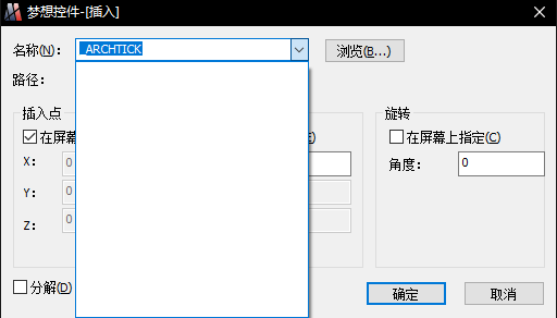
在导入之前,我们可以看到的是“插入图块”界面没有任何可用图块,如下图:
我们点击“块”按钮,代码执行到此处:
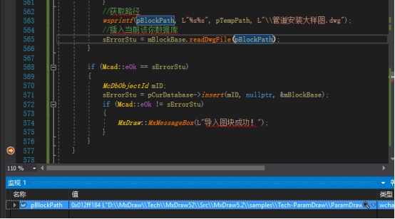
可以看到的是我们读取到了“pBlockPath”该路径中的一张dwg图纸,即为此图纸:

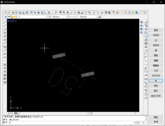
我们继续执行,可以看到视区会出现如下图块,这便是我们下段代码添加的第一个图块,
代码如下:
	//插入一个图块
	{
		McDbBlockTable * pTable;
		pCurDatabase->getBlockTable(pTable, McDb::kForRead);

		McDbBlockTableIterator * pIterator;
		pTable->newIterator(pIterator);
		std::auto_ptr<McDbBlockTableIterator> spIterator(pIterator);//该迭代器的生命周期绑定到智能指针

		if (pIterator)
		{
			McDbObjectId mBlockTableID;
			//遍历所有记录
			for (; !pIterator->done(); pIterator->step())
			{
				//获取ID
				pIterator->getRecordId(mBlockTableID);

				McDbObjectPointer<McDbBlockTableRecord> spBlockRec(mBlockTableID, McDb::kForRead);
				auto d = spBlockRec.openStatus();
				if (Mcad::eOk == spBlockRec.openStatus())
				{
					McDbBlockReference* pBlock = new McDbBlockReference;
					auto mLayerID = CreateLayer(pBlock);

					pBlock->setBlockTableRecord(spBlockRec->objectId());
					pBlock->setPosition(McGePoint3d(0, 0, 0));
					pBlock->setScaleFactors(1.0);
					pBlock->setRotation(1.0);
					pBlock->setLayer(mLayerID);

					AddToSpaceAndPutToView(pBlock);

					break;
				}
			}
		}
	}
我们再次打开“插入图块”界面:
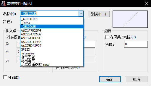
可以看到的是添加了一些图块,这些图块真是我们添加的bin目录下的图纸里的图块
填充在MxDrawCAD控件下为一个实体类:
class ARXDLL McDbHatch : public McDbEntity
通过调用调用默认构造函数进行实例化:
McDbHatch * pHatch = new McDbHatch;
我们对其进行设置:
	McDbHatch * pHatch = new McDbHatch;
	auto mLayerID = CreateLayer(pHatch);

	if (pHatch)
	{
		pHatch->setHatchStyle(McDbHatch::kNormal);
		pHatch->setHatchObjectType(McDbHatch::kHatchObject);
		pHatch->setPatternScale(1.0);
		pHatch->setPattern(McDbHatch::kPreDefined, L"SOLID");
		pHatch->setColorIndex(MrxDbgUtils::kBylayer);
		pHatch->setLayer(mLayerID);

		McGePoint2dArray vertices;
		McGeDoubleArray bulges;

		vertices.append(McGePoint2d(0, 0));
		bulges.append(0);
		vertices.append(McGePoint2d(10, 0));
		bulges.append(0);
		vertices.append(McGePoint2d(10, 10));
		bulges.append(0);
		vertices.append(McGePoint2d(0, 10));
		bulges.append(0);

		pHatch->appendLoop(McDbHatch::kPolyline, vertices, bulges);

		AddToSpaceAndPutToView(pHatch);
	}
在上述代码中,我们对其设置了setPattern,其中的的二个参数我们设置为L”SOLID”,这是因为我们需要使用该类型图案,样式如下:
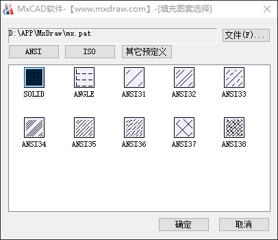
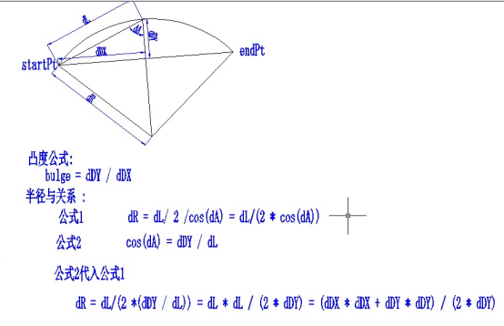
我们还设置了边界数组与边界凸度,边界数组即为填充的边界坐标,而凸度我们设置成了0,凸度的含义如下图所示:
图片在MxDrawCAD控件下为一个实体类:
// -------------------------------------------------------------------------
// Summary:
//  光栅图形定义类型
// -------------------------------------------------------------------------
class ARXDLL McDbRasterImageDef : public McDbObject
// -------------------------------------------------------------------------
// Summary:
//  光栅图片类,该类用于在CAD中显示光栅图形
// -------------------------------------------------------------------------
class ARXDLL McDbRasterImage : public McDbImage
class ARXDLL McDbImage : public McDbEntity
我们通过如下的方式将图片显示至视区:
 	wchar_t sFileName[200] = {};
 	{
 		wchar_t pTempPath[200] = {};
 		auto sPath = GetCommandLine();
 		sPath++;
 		size_t iRank(wcslen(sPath));
 		for (; iRank > 0; iRank--)
 		{
 			if (L'/' == sPath[iRank] || L'\\' == sPath[iRank])
 			{
 				wmemcpy(pTempPath, sPath, iRank);
 				break;
 			}
 		}
 		//获取路径
 		wsprintf(sFileName, L"%s%s", pTempPath, L"\\Watermark.png");
 	}

	double dW = 10;
	double dH = 10;

	{
		// 得到相关图片消息
		Gdiplus::Image tmpImage(sFileName);
		if (tmpImage.GetLastStatus() != Gdiplus::Ok)
		{
			acutPrintf(_T("n 图片文件不能打开"));
			return;
		}
		dW = tmpImage.GetWidth() / 10.0;
		dH = tmpImage.GetHeight() / 10.0;
	}

	CString sName = sFileName;
	if (sName.IsEmpty())
	{
		return;
	}

	// 在字典对对象中创建图片定义对象。
	McDbDatabase* pDatabase = Mx::mcdbHostApplicationServices()->workingDatabase();
	McDbDictionary* pDict = NULL;
	pDatabase->getNamedObjectsDictionary(pDict, McDb::kForWrite);
	if (pDict == NULL)
		return;
	//


	McDbObjectId imageDictId;
	if (pDict->getAt(MCAD_IMAGE_DICT_NAME, imageDictId) != Mcad::eOk)
	{
		// 创建该字典.
		McDbDictionary* pImageDict = new McDbDictionary;
		if (pDict->setAt(MCAD_IMAGE_DICT_NAME,
			pImageDict, imageDictId) != Mcad::eOk)
		{
			delete pImageDict;
			pImageDict = NULL;
		}
		else
		{
			pImageDict->close();
		}
	}

	pDict->close();

	McDbObjectId imageDefId;
	if (!imageDictId.isNull())
	{
		McDbObjectPointer<McDbDictionary> spImageDict(imageDictId, McDb::kForWrite);
		if (spImageDict.openStatus() == Mcad::eOk)
		{
			if (spImageDict->getAt(sName, imageDefId) != Mcad::eOk)
			{
				//添加图象定义.
					McDbRasterImageDef* pNewImageDef = new McDbRasterImageDef;
				pNewImageDef->setSourceFileName(sFileName);

				if (spImageDict->setAt(sName,
					pNewImageDef, imageDefId) != Mcad::eOk)
				{
					delete pNewImageDef;
					pNewImageDef = NULL;
				}
				else
				{
					pNewImageDef->close();
				}
			}
		}
	}

	if (!imageDefId.isNull())
	{
		// 创建Image实例。
		McDbRasterImage* pImage = new McDbRasterImage;
		McGeVector3d uCorner = McGeVector3d::kXAxis * dW;
		McGeVector3d vOnPlane = McGeVector3d::kYAxis * dH;

		pImage->setOrientation(McGePoint3d(0, 0, 0), uCorner, vOnPlane);
		pImage->setImageDefId(imageDefId);

		auto mLayerID = CreateLayer(pImage);
		pImage->setLayer(mLayerID);

		MrxDbgUtils::addToCurrentSpaceAndClose(pImage);
	}
上端代码即为将bin目录下的水印显示至视区
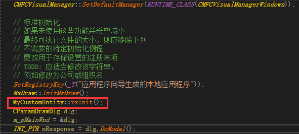
对于自定义实体,我们以同样的方式进行添加,首先添加我们在“自定义实体”教程中准备的文件:
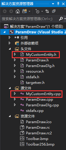
然后再InitInstance函数中进行如下的注册:
MxDraw::InitMxDraw();
如下图所示:
之后就可以使用了,我们在按钮事件里添加如下代码:
	{
		MyCustomEntity * pEnt = new MyCustomEntity(McGePoint3d(0, 0, 0), 10);
		SetEnt<MyCustomEntity>(256, _T("ByLayer"), pEnt);//颜色随层,线型随层
	}

	{
		MyCustomEntity * pEnt = new MyCustomEntity(McGePoint3d(0, 20, 0), 10);
		SetEnt<MyCustomEntity>(0, _T("ByBlock"), pEnt);//颜色随块,线型随块
	}

	{
		MyCustomEntity * pEnt = new MyCustomEntity(McGePoint3d(20, 0, 0), 10);
		SetEnt<MyCustomEntity>(2, _T("BORDER"), pEnt);//黄色,BORDER线型
	}
可以看到的是,对于参数化绘图,我们只需要将要添加的实体进行实例化(new),然后MrxDbgUtils::addToCurrentSpaceAndClose即可,对于需要修改的实体,我们通过使用智能指针的方式打开,然后修改即可。